6/28/2009

Homemade Anti Backlash Nut for sherline machines

Since last summer, I tried to make anti backlash nut for my machines.
There are two major sizes of drive screws on my machines. As my machines are in metric scale, sherline cut the standard M6 1mm pitch thread on the drive screws and nuts, but they are using the 0.25 inch (6.35mm)and 0.375 inch (9.525mm)diameter stock to make the screws. This result in unique specifications of threads.

At the very beginning, I plan to make a brass anti backlash nut with center expansion spacer; the spacer was driven by a torsion spring. But the overall size of the nut was so small that I was hardly to cut the parts out. (I will need to use 0.5mm spring wire to make the torsion spring in order to keep the overall size under the limit.)

During making the nuts, I’ve tried different methods to cut the internal and external threads. I’ve spent 2 weeks to grind the LH and RH internal threading tool. Although I can cut the thread as I want, the process was very slow, especially there is no power assist when using the threading attachment on my lathe.


Thus, I decided to make my own tap. I cut the taps from sliver steel, and try to heat treat them on a household gas strove. The heat treating result was not very good, the tap wear faster than my expectation.

In my design, I want the nuts can be:

1, Easy to cut/make
2, Flange mounting
3, Little / no modification on the machines
4, Last reasonably longer
5, Self compensation for the wearing


Brass was a bit hard for my homemade tap, so, I am going to use a soft and wear resistant material, that is delrin.
I also decide to use an expansion spring to replace the expansion spacer. Although the spring will push the nuts at all time, introducing loading on the nuts and screw. The thread pitch is 1mm, that’s mean if the spring push out 0.5mm for wear compensation, the nuts are going to be replaced. And 0.5mm pre-compression will not introduce large amount of loading. Moreover, my machines are light duty machines, the resistant introduced by work tables and dovetail slides are only several kgs.


I am going to add this nut on the cross slide of my lathe first, as the cross slide don’t has any anti backlash devices. I can also use this axis to test my anti backlash nut.


Hopefully the delrin nuts can last for at least 500 hours.

7/08/2008

Gib fitting

This is properly the first problem I've found in this lathe. When I wind the cross slide hand wheel, the cross slide moving with rocking. And this can be easily observe by eyes!

Then I decide to take the cross slide off and see what's wrong.
And this is...

The gib was a bit higher than the dovetail. That means, the cross slide cannot sit down properly on the saddle.
What I am going to do is file the gib down...
Now, the cross slide can sit down properly on the saddle, but when I insert the gib deeper into the space, rocking movement come back again.


When I carefully look at the gib and the dovetail, I find that, the gib is more likely to be less than 55 degree of the dovetail.
Put it deeper into the taper space will press it upward and push up the cross slide again.

Now, I've the handy epoxy putty, put a thin layer on the non-sliding surface of the gib.

Finally, the rocking motion become unseeable.
Of course, I will need to check the cross slide by level or DTI when higher accuracy is needed.

7/07/2008

Lead screw end support bearing

After I've taken out the lead screw, I found that, the end which close to the headstock was directly inserted into a tube.

Without any bushing or bearing support, I can see there has a scrap mark on the inner surface of the tube. And it was definitely a thread scrapped mark!


Luckily, I find a 12x8mm bearing on hand, and...
Turn the lead screw end down to 8mm and bore up the tube to 12mm...

And that's it, you can use what ever spec. of bearing , as long as it is not larger than the tube (0.625 inch), cheap and easy to find for you.

6/02/2008

Precision machinist's level

This device is actually a more sensitive and accurate water level.

Which has a precision ground bottom surface, normally with V shape channel at the bottom for standing on round objects.

With a precision made water level scale. This level can show 4 seconds of inclination change.


You don't need to use a flat reference surface to zero it. Just simply place it on a clean, rigid surface.Shim the surface to roughly flat level, then the water bubble will move to somewhere in between of the scale.

In this case, I've placed my level on x-rail.Waiting for a while, let the water bubble steady down, record the reading. Then turn the level in 180 degree opposite orientation and sit down on the same surface.

I've used the edge of the saddle for position reference, so I can put the level back to the same position.Again, waiting for a while, let the water bubble steady down, record the reading. If the readings are the same, the level was zeroed.

If you have reading different, divide it into two, that's the amount of inclination you need to adjust for zeroing this level.

Adjust the zeroing screw or set screw on the level, try to achieve half of the reading different and let the water bubble move from larger reading side to smaller reading side.

Finally, the level will be zeroed.


5/11/2008

Run out of 3-jaws chuck

Normally, no one will re-chuck the work piece to turn both ends, unless it is absolutely necessary. Especially re-chucking the 3-jaws self centering chuck will make you get into trouble.

But, checking the run out is another thing; it can be performing very easily.
I am going to use an edge finder to check the run out. Some people will use a drill rod, or the clamping end of the drill bit. All of them are work, as long as the testing rods are straight and concentric.


Because the chuck was sitting on the spindle shoulder, if you didn’t check the flatness of the shoulder, you can put the probe closer to the chuck to eliminate the whirling effect.

If the testing rod has marking on it, it’s better to avoid clamping and touching on the marking.

I was surprised that my chuck has 48 microns run out. It was a bit large. What I can do now is dissemble and clean it; to see if I can make it better or not.
3-jaws self centering chuck was dissembled and cleaned

Re- grease the chuck
Assemble the chuck
Finally, I’ve got 13 microns run out; it’s a much reasonable result!
Run out of 3-jaws self centering chuck can be varying to different chucking diameters duel to the structure of the chuck.

My suggestion is after you’ve confirmed the center of spindle was parallel to the X rail; you can turn a shock down to the common working diameter of your projects, cut off it from the chuck, and you will have your own run out testing rod.

Magnetic base mount

Sherline makes tables from extruded aluminum; I need a little piece of steel plate for the magnetic base of dial test indicator.


After I’ve finish this plate, I find that, if I put screws in both of holes, there will have no space for the magnetic base.


So, I can only remove the front screw, let the weight of magnetic base press down the steel plate. It was rigid enough for my works. I suggest using a larger steel plate to provide enough space for your magnetic base.

Lathe Spindle

I am going to check and adjust my lathe first, and then the mill will be followed.
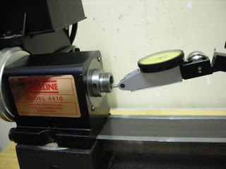
First thing I am going to check is the spindle. There are two critical matching surfaces.


1. The shoulder; inclination and flatness check. I have 10 microns deviation, it can form 0.086mm radius turning error at the middle of x-axis (8.66”)


2. The concentricity of the taper hole. Luckily, my indicator doesn’t move! This taper was made in very good quality!


For the first problem, I‘ve used miniature file and no.800 water sandpaper and try to flatten the shoulder. Finally, I‘ve made the deviation down to 2 microns with 45 minutes hand work. The error becomes -0.017mm radius at the middle of x-axis. Of course, if you have patient, you can make it much closer to zero.